Difference between revisions of "DesignerUserGuide"
doc>Vromav |
m (1 revision imported) |
(No difference)
| |
Latest revision as of 06:37, 23 November 2020
Developer Studio user guide
RunaWFE Free Workflow System (BPMS) Version 4.5.0
© 2003 - 2015, Consulting Group Runa
© 2015 - 2025, "Process Technologies" Ltd, this document is available under GNU FDL license. RunaWFE Free is an open source system distributed under a LGPL license (http://www.gnu.org/licenses/lgpl.html).
Introduction
Developer Studio is a graphical process designer for the open source system of business process management RunaWFE. Developer Studio is a part of the open source project RunaWFE and is distrubuted free of charge under the LGPL lisence. Developer Studio can work on different platforms (Linux, Windows, etc). Developer Studio is free to download along with source code from the sourceforge portal http://sourceforge.net/projects/runawfe/files and from Github https://github.com/processtech. This document describes how to develop business processes with the help of Developer Studio. Developer Studio generates .par archive files. Each .par file contains business process definition written in jPdl language. Reference documentation for jPdl language can be found at http://www.jboss.org/jbossjbpm/jpdl_documentation.
Installation and running guide
Developer Studio is distributed as a part of the RunaWFE system in one of the following ways:
- In a set of specialized distributives for specific operating systems
- In a java-compiled set of .zip files
- In a source files set
How to install and run DeveloperStudio is descibed in Installation Guide.
Creating new Developer Studio project
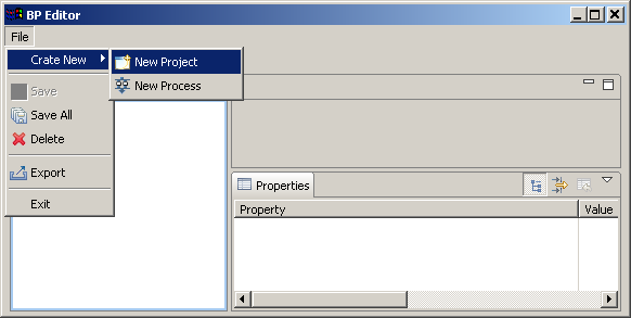
- In Developer Studio select from menu File > Create New >New Project.... to open the New Project wizard.
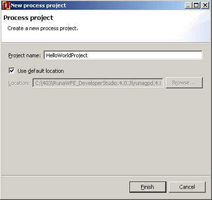
2. Enter the project name “HelloWorldProject”.
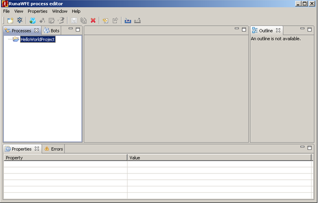
The HelloWorldProject project will be created.
Creating HelloWorld process
The process consists only of two nodes: the start-state and the stop-state.
The process scenario
- On process start HelloWorld starting form appears.
- When “complete” button on the form is pressed the process immediately ends.
Process graph creation
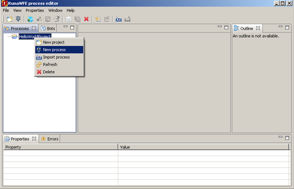
Open context menu by the right mouse click on HelloWorldProject, then click on New Process menu item.
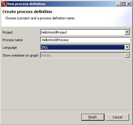
Enter HelloWorldProcess as the process name.
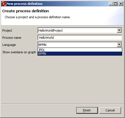
Available languages are JPDL and BPMN, select JPDL
Click "Finish". HelloWorldProcess will be created.
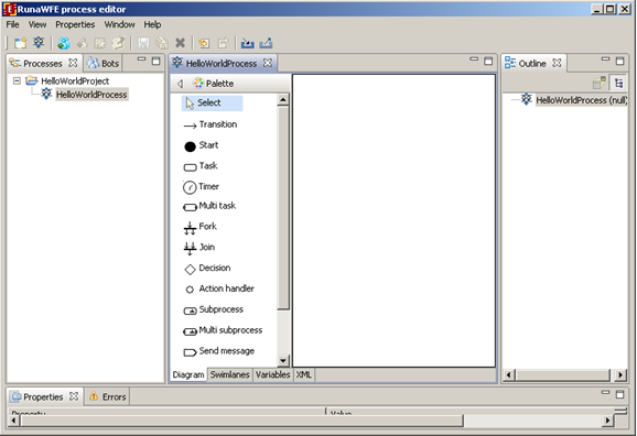
Double click on the HelloWorldProcess. The process diagram window will appear:
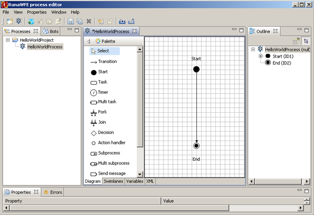
Click on menu Properties/Show Grid, the grid will appear. Click on “Start” element on the Palette, then click on diagram window. The Start state will appear on diagram window. Similarly place the End state on diagram, then click on “transition” element on the palette and connect Start and End states.
Click on menu Properties/Show Grid, the grid will disappear. In the corresponding fields of Properties tab enter a short description of the process (optional) and an icon for the process (optional). The process graph is ready.
Swimlanes creation
Introduction to swimlanes
Swimlanes corresponds to business process roles. In JBoss jBPM swimlane is a special business process variable. Every state has swimlane associated with it. The start state behavior regarding swimlane differs from the other states behavior. It doesn't use initializer. The start state fills start state swimlane with user that starts the process. The end state has no swimlane associated. Other states use associated swimlanes to determine who can execute the task of the state.
Swimlanes for HelloWorld process
The process has only start and end states, so there is a single swimlane in the process.
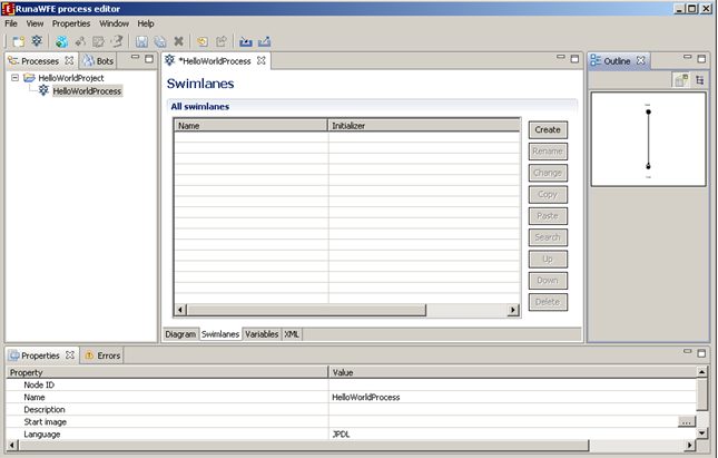
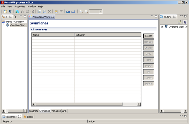
Click Swimlanes tab. You'll see the following:
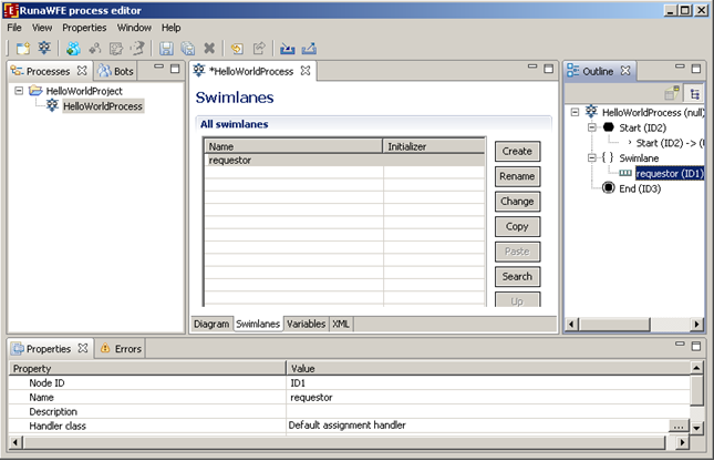
Then click Create button. The creating swimlane form will appear. Enter swimline name “requester”.
Click Ok.
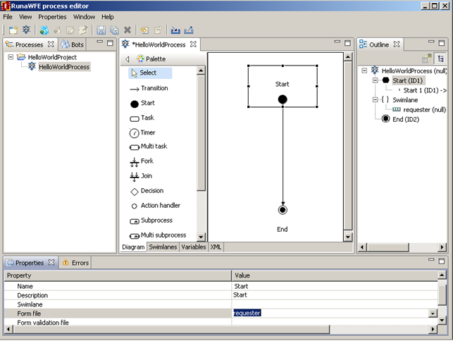
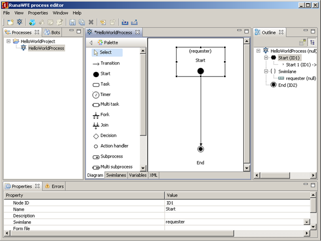
Click Diagram tab, click start state and choose “requester” as Swimlane value in properties view.
The name of the swimlane will appear above the name of the task on the diagram
Graphical form creation
Forms
Every task that is not intended for a bot should have a corresponding form. HTML tags are used in forms. Starting from Developer Studio version 4.0 only html forms with ftl (FreeMarker) tags are available for creation.
FreeMarker tags can be used for customized tags and for business process variables output in forms.
FreeMarker description can (for example) be found here - http://ru.wikipedia.org/wiki/FreeMarker
HTML forms with <customtag> depricated and supported for backward compatibility, but it´s impossible to create a new form of this type.
There will be an error message if tried:
The <customtag> tag have the following attributes:
- var – process variable name
- delegation – name of Java class, used for the variable value rendering
Form file creation
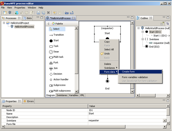
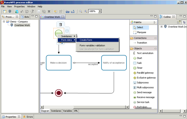
HelloWorld process has no variables and only one form – start form. Right click start state then click on "Form" menu item and choose "Create form" command from next level menu.
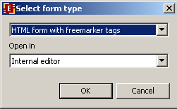
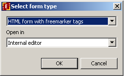
The dialog will appear. Choose form type.
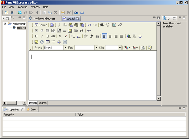
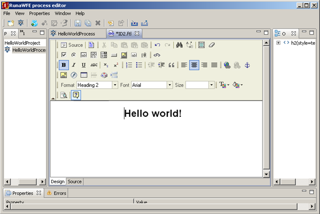
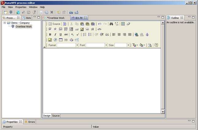
After the form editor opening click the "Design" tab.
In the form editor type in: Hello World! Choose the font, size and align.
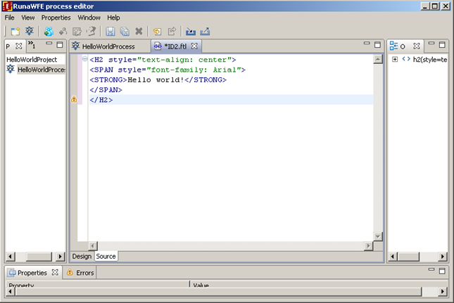
Click on "Save" icon to save you changes. Choose "Source" tab if you want to see the html code of the form.
Process definition archive creation
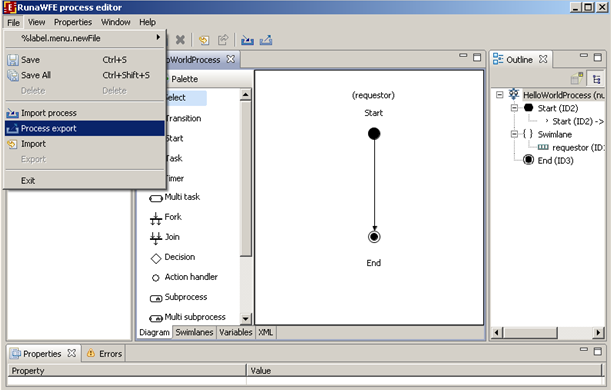
Select HelloWorldProcess, then open menu item File/Process export (or use and icon in the tool bar) to create .par process archive.
It's possible to export process into file as well as right into WFE Server. In this case let's export into file, export into server will be explained later on in this document.
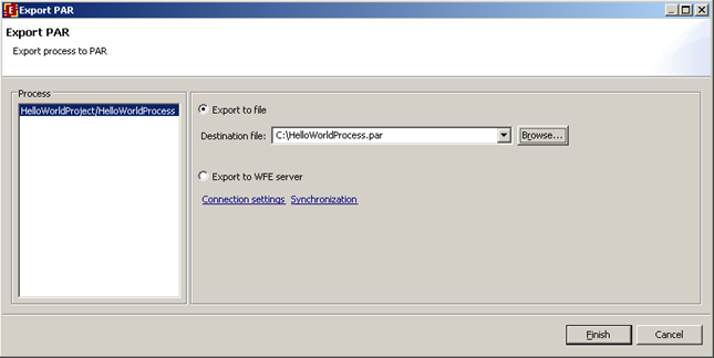
So in the dialog choose export to file, click "Browse...", select folder and name the file with business process archive:
Then click “finish” button. The HelloWorld process file will be generated.
Deployment into RunaWFE environment
Login into RunaWFE web interface as Administrator (The default Administrators password is wf, see RunaWFE manual for details).
Go to “start process” menu. Press deploy process definition.
Note:In order to deploy a process you must have Process Definition permission on System (can be granted via system menu).
Press browse button to select process definition archive. Choose the previously formed HelloWorldProcess.par file from the file system. Then type the name of the new process type: demo. Click "Deploy process definition".
HelloWorldProcess is now deployed into the system.
Running Hello World process
Click on process name in “start process” menu. You'll see the start form:
Click on “Start” button. The “Hello World” process starts and immediately ends. You can see the process instance in the “Started processes” menu:
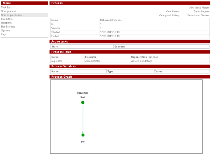
Click on the process name to view process properties:
Creating Overtime Work process
The process scenario
Manager offers an over time work to employee. Employee accepts or rejects the offer. Then manager receives the corresponding notification.
It is supposed that all managers are members of group “manager” and all employees are members of group “staff”.
Process graph creation
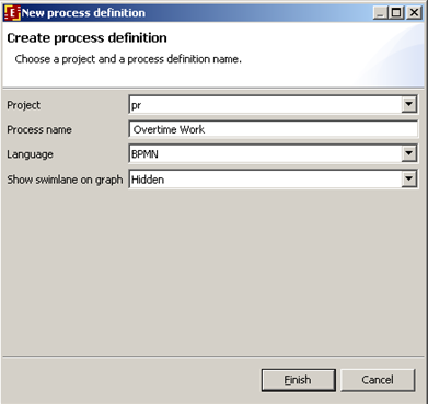
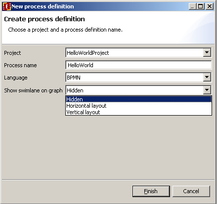
Create a new project. Open context menu by right clicking on project, then click on New Process command. Enter “Overtime Work” as the process name. This demo process was developed on BPMN. Choose bpmn language, show swimlane on graph - hidden. (The feature of swimlanes shown on business process graph will be described later on)
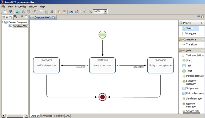
Double click on the “Overtime Work”. The process diagram window will appear. By clicking at palette elements and process diagram window create the following graph for business process (also it is necessary to rename states (in properties view)):
To change an element name, select an element by clicking on it, then click the element once more. For transitions from the choice state "Is accepted?" enter their explicit names "accepted" and "rejected" in their properties.
Swimlanes creation
Swimlanes overview
Swimlanes behavior in StartState and EndState was described in “Creating Hello World process” section. Other states use associated swimlanes to determine who can execute the task.
Swimlane is a special type of business process variable. It may be initialized with the ID of a group or an actor at any moment of process execution. The swimlane of the node has to be initialized by the time when execution enters this node. If the current state's swimlane is initialized with the actor, then only one executor (this actor) receives task corresponding to the state. If the swimlane is initialized with the group, then all the members of the group receive task corresponding to the state. But only one member of the group is able to execute the task, the one who is the first to press "Task is done" button. After it the additional initialization occurs and the swimlane contains not the group but this actor.
If the current state's swimlane is not initialized, then the special mechanism is used to decide who can perform the task. This mechanism is called orgfunction. Orgfunction is defined by special kind of Java class and parameters. This class on the basis of parameter values generates a list of executors who can execute the task. If an executor is in the list, the task, associated with the current state, is shown as available in his/her tasklist. The first actor who executes the task initialize swimlane with his/her ID.
There is another way to initialize swimlane. User ID can be assigned to process variable with name of swimlane. In this case orgfunction is not needed and swimlane is initialized by variable setting (e.g. via the form).
Developer Studio has special forms developed to work with the orgfunctions. To pass a parameter to orgfunction you should inclose it in special braces -- ${} (e.g. ${<variable name>}).
Swimlanes for «over time work demo» process
Business process has two swimlanes:
- manager
- staffrole
| Swimlane description: |
| Swimlane | Description |
| manager | Manager who starts the process |
| staffrole | The employee who is selected by manager in the start form and who is asked to work overtime. |
| Correspondence between business process nodes and swimlanes |
| Node | Swimlane |
| Offer an overtime work | manager |
| Make a decision | staffrole |
| Notify of rejection | manager |
| Notify of acceptance | manager |
Swimlanes creation
Click on "swimlanes" tab.
In the opened page press "Create" button.
In the opened dialog type swimlane name «manager» and press «ОК». This swimlane is used in the start node and the swimlane will be initialized with the user who starts the process. So there is no need to specify the initializer.
Similarly create «staffrole» swimlane.
Note. Initializers settings will be explained separately later on in this document.
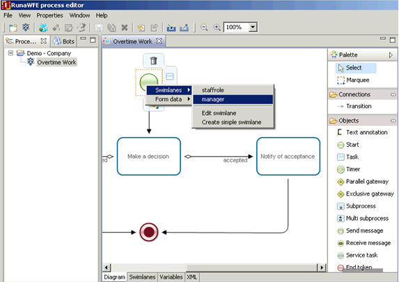
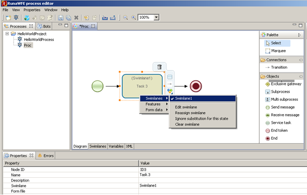
Open "Diagram" tab, select the start node “Offer an overtime work”. In the properties tab click on the right side of the "swimlane" property. In the given list select “manager”. You can also use "swimline" item from the popup menu instead. Right click on the start node and select "manager" from the list under "swimlane" item.
Similarly set swimlanes for all the rest of the graph nodes.
Creating variables
Variables description and initialization
| The following variables are used in the Overtime Work process: |
| Variable | Type | Description |
| since | DateTime | DateTime when overtime work starts |
| till | DateTime | DateTime when overtime work ends |
| reason | String | Reason |
| comment | Text | Comment |
| staff_person_comment | Text | Employee comment |
Variables
- since
- till
- reason
- comment
are initialized in StartState “Offer an overtime work”.
Variables
- staff_person_comment
are initialized in State “Make a decision”
Variables creation
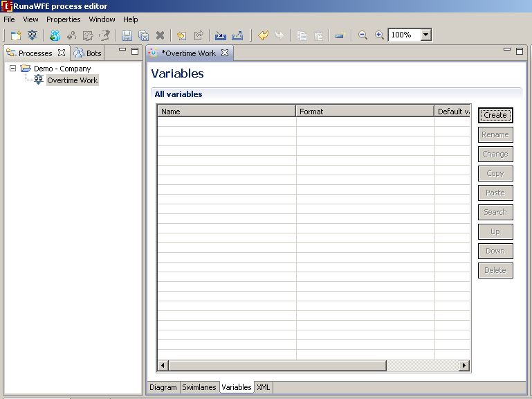
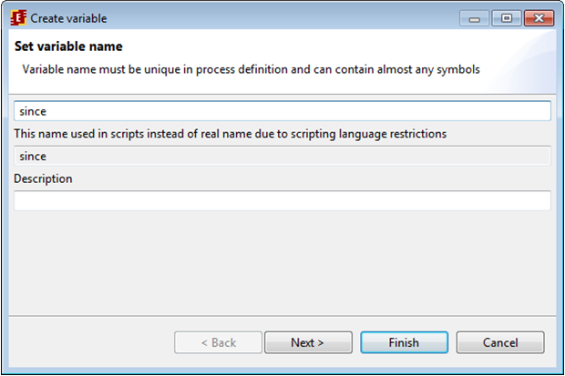
Click on “Variables” tab. Click “Create” button.
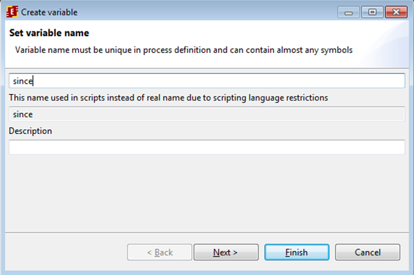
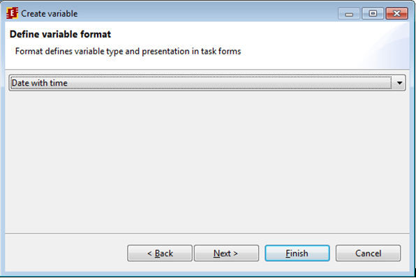
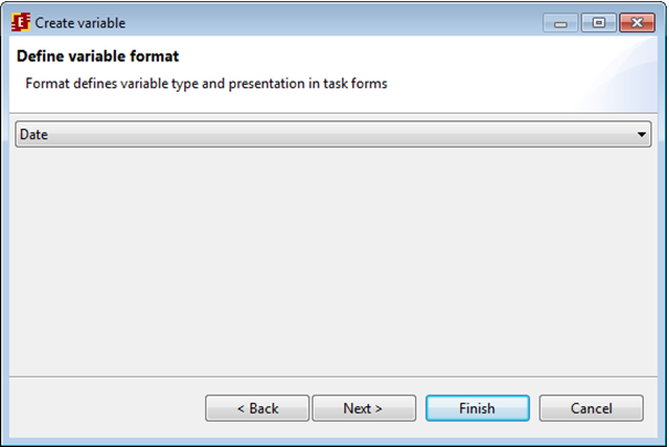
Type in the variable name "since" and click NEXT, then choose date with time as variable format.
Similarly create all the others variables of the business process.
Graphical forms creation
RUNA WFE forms description
A form must correspond to each graph node with nonbot swimlane. Each form is saved in a separate file. The html forms extended with FreeMarker tags can be used. Html forms extended with <customtag> cannot be created since Developer Studio version 4.0.
Extention tags are used to present specific control elements and to present business process variables values in forms.
FreeMarker description can be found here (for example) - http://ru.wikipedia.org/wiki/FreeMarker
In "Overtime Work" HTML forms with FreeMarker (FTL) tags are used.
| Tags used in "Overtime Work": |
| Freemarker tag | Description |
|---|---|
| Selection from group, GroupMembers | Shows the list of group members. Group name can be specified via variable or by value. Also a swimlane that will be initialized with the selected group member ID must be set. In "Overtime Work" “staff” group is used, it is set by value. The selected group member is used to initialize “staffrole” swimlane. |
| Variable input, InputVariable | A field is created to input variable value according to its type |
| Variable output, DisplayVariable | Output the variable value in read only mode. |
Creating forms with the help of Developer Studio
Click on “Offer an overtime work” state, then choose “Forms/Create form”.
Choose the type of form you want to create. Choose the form type "html form with freemarker tags"
After choosing create (or edit) form option the graphical form design tab will open:
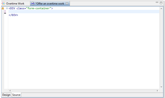
Set the html code on the "Code" tab.
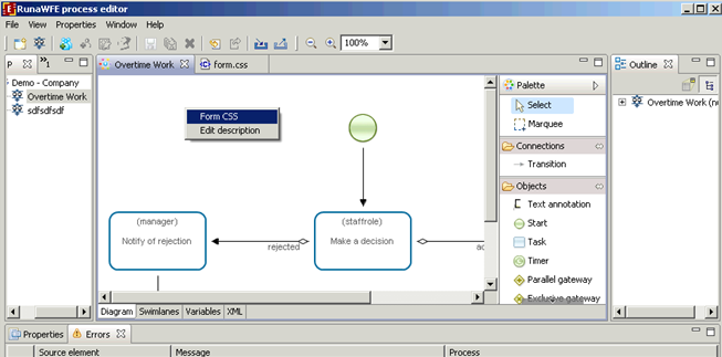
If you want to use styles on form, right click on empty space of the process graph and select "Form CSS"
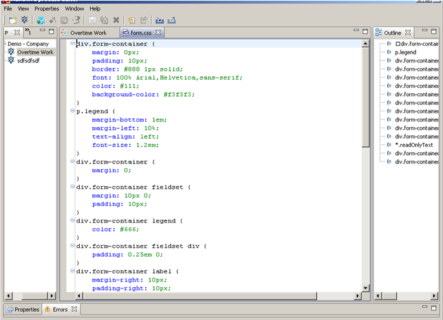
In the opened window you can edit form.css file, set styles in it, for example:
div.form-container {
    margin: 0px;
    padding: 10px;
    border: #888 1px solid;
    font: 100% Arial,Helvetica,sans-serif;
    color: #111;
    background-color: #f3f3f3;
}
p.legend {
    margin-bottom: 1em;
    margin-left: 10%;
    text-align: left;
    font-size: 1.2em;
}
div.form-container {
    margin: 0;
}
div.form-container fieldset {
    margin: 10px 0;
    padding: 10px;
}
div.form-container legend {
    color: #666;
}
div.form-container fieldset div {
    padding: 0.25em 0;
}
div.form-container label {
    margin-right: 10px;
    padding-right: 10px;
    width: 150px;
    display: block;
    float: left;
    text-align: right;
    position: relative;
}
div.form-container label em {
    position: absolute; right: 0;
    font-size: 120%;
    font-style: normal; color: #C00;
}
div.form-container input:focus, div.form-container textarea:focus {
    background-color: #FFC;
    border-color: #FC6;
}
div.form-container input {
    width: 300px;
    padding-left: 5px;
}
div.form-container select {
    width: 300px;
}
div.form-container textarea {
    width: 300px;
    height: 100px;
    padding: 5px;
    overflow: auto;
}
.readOnlyText {
    background-color: #f3f3f3;
}
div.form-container div.controlset label, div.form-container div.controlset input {
    display: inline;
    float: none;
    width: auto;
}
div.form-container div.controlset {
    margin-left: 170px;
}
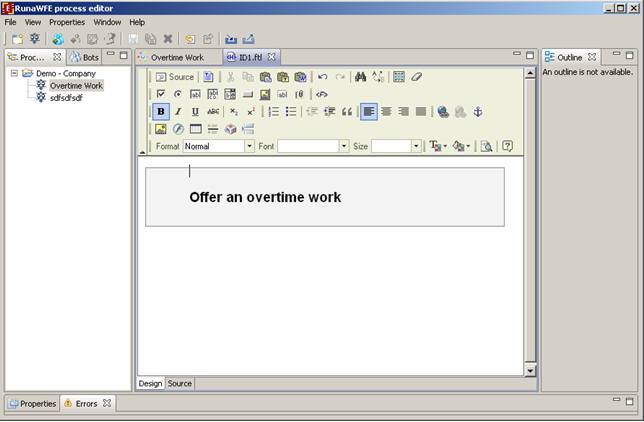
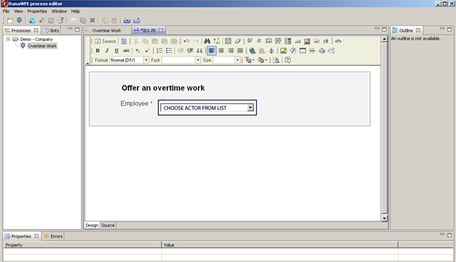
On the "Design" tab type in «Offer an overtime work».
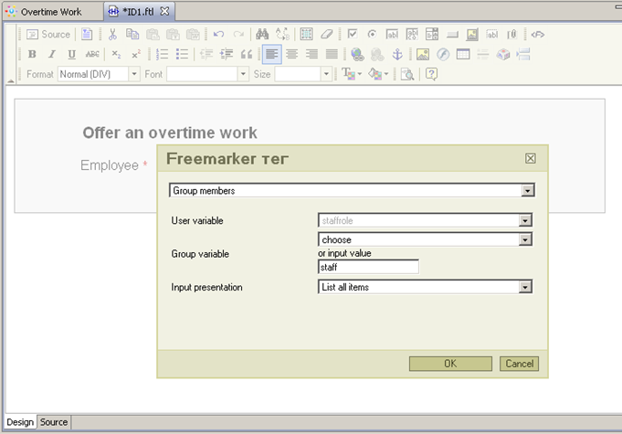
On the next line type in «Employee *» and click ![]() element. Select "Group members" tag, select "staffrole" as "User variable" and type in value "staff" in the "Group variable" field:
element. Select "Group members" tag, select "staffrole" as "User variable" and type in value "staff" in the "Group variable" field:
Click "Ok". There will be "Choose actor from list" element on the form:
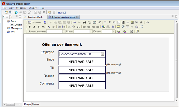
Use "InputVariable" tag to create input elements for the other business process variables:
- since
- till
- reason
- comment
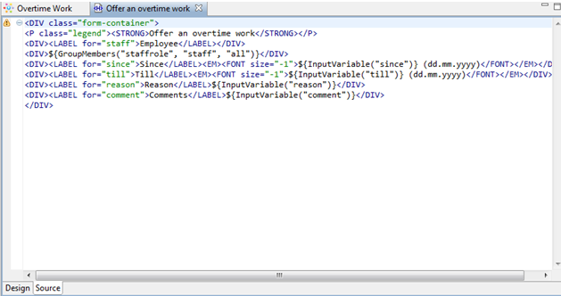
Note. If you open "Code" tab you can see html code of the page:
Similarly other forms for other action-nodes are created.
- Make a decision
- Notify of rejection
- Notify of acceptance
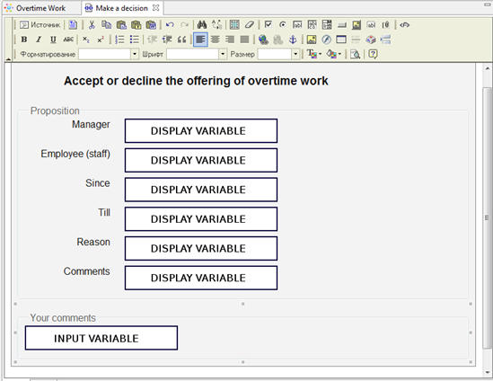
«Make a decision» form:
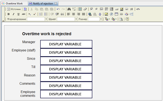
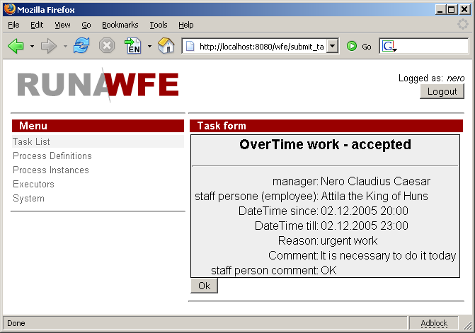
«Notify of rejection» form:
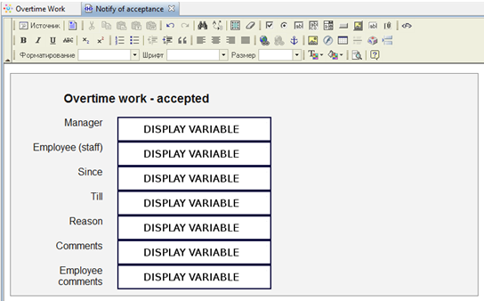
«Notify of acceptance» form:
Form variables validation
Form elements might require input or be optional. Also there can be global validation restrictions for a set of form elements. E.g. "Since" date must be earlier than "Till" date. Besides there can be type specific restrictions: more or less than a given number for numeric type, the length of string limit for strings, etc.
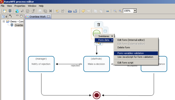
To set validation for "Offer an overtime work" form right click the state on the graph and choose Form data -> Form variables validation from the popup menu.
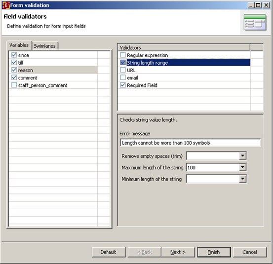
In this form all the business process variables are shown. All variables used in the form are checked. If you uncheck variable it will not be initialized when form is processed.
You can select validators for the selected variable. When you click on validator name you can see and set validator options below:
In this case, for example, the "string length range" validator max length option is set to 100 characters and error message is set to "Length cannot be more than 100 symbols".
If you want to validate several variables together after setting all separate validators click "Next".
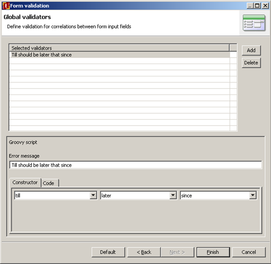
In this dialog you can set global validators. For example, "Till" date value cannot be before "Since" date value:
Note. If validation rules contain errors the process will not deploy. If there are only warnings in the validation rules the process will deploy.
Error types with forms:
- No form validation file found. (While the form file is present) - ERROR
- No form variable found in process variables - ERROR
- No form variable found in the validation file - WARNING
Process definition archive file creation
The export of "Overtime Work" process into the .par file is completely similar to that of "HelloWorldProcess". Note that in order to run "Overtime Work", you should previously create groups of users:
- manager
- staff
- all
add users to those groups and grant corresponding permissions in Workflow system.
Creating Vacation demo process
The process scenario
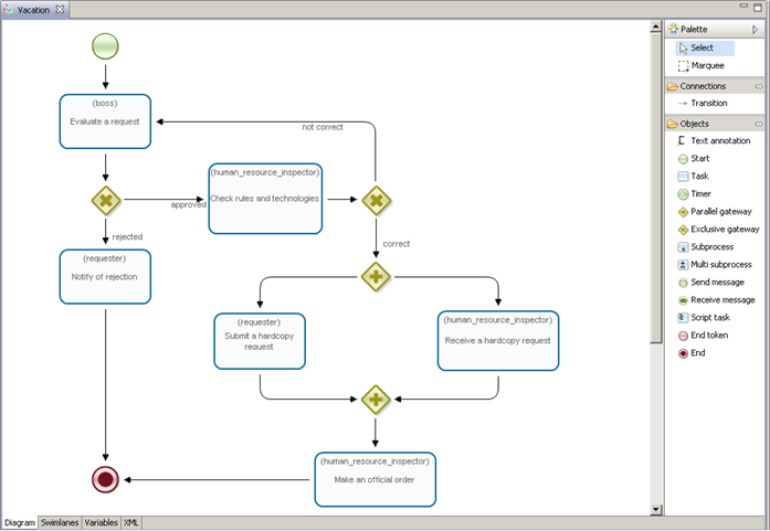
An employee submits a request for a vacation. The employee's boss approves or rejects the request. If the request is rejected the employee receives a notification. If the request is approved, then a request to the human resource department is formed and a human resource inspector makes a check if all the rules and technologies are followed correctly. If the human resource inspector doesn't approve the request it returns to the employee's boss, else if all the rules and technologies are followed correctly the business process passes to forming a hard copy request for a vacation and to signing the official order. The employee receives a task to "submit a hard copy request" to the HR department and simultaneously the HR inspector gets a task to "receive a hard copy request". After performing this task the HR inspector receives task to "make an official order". When all these tasks are performed the business process ends.
Process diagram creation
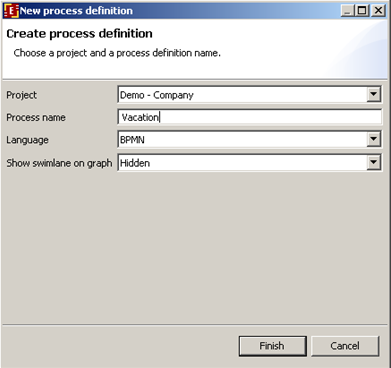
Create a new project, then right click on it and select "new process" command. Type "Vacation" as the new process name. This process will be developed on BPMN language, choose bpmn.
Make a double click on the "Vacation" process in the project process list opening the business process diagram tab. Selecting and applying the palette elements draw the following diagram of the business process:
Use the following elements: exclusive gateways, tasks, parallel gateways, start and end.
To change element name, in case they differ from default, make a click on the element change the name in element properties. For the transitions that come out of the exclusive gateways assign names «approved»/«rejected» and «not correct»/«correct» by clicking on them and changing their names in property tab in the bottom of the screen.
Creating swimlanes
Creating swimlanes for Vacation process
In this business process there are 3 swimlanes:
- requester
- boss
- human resource inspector
| Swimlane's description: |
| Swimlane | Description |
| requester | An employee who submits a vacation request |
| boss | A boss of the employee who started the business process |
| human resource inspector | One of the employees of the HR department (human resource group), who executes the check of the rules and technologies for the request and prepares and sees that the official order is signed. |
| Swimlanes and activity nodes relation: |
| Node | Swimlane |
| Request for a vacation | requester |
| Evaluate a request | boss |
| Notify of rejection | requester |
| Check rules and technologies | human resource inspector |
| Submit a hardcopy request | requester |
| Receive a hardcopy request | human resource inspector |
| Make an official order | human resource inspector |
Swimlane creation
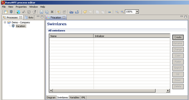
Click on the Swimlane tab.
On the appeared page click on the "Create" button.
Type in swimlane name "requester" and click "OK". This swimlane is used in the start state so there´s no need to specify initializer, it is initialized by the user who starts the process.
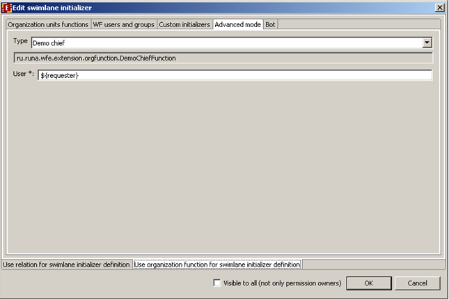
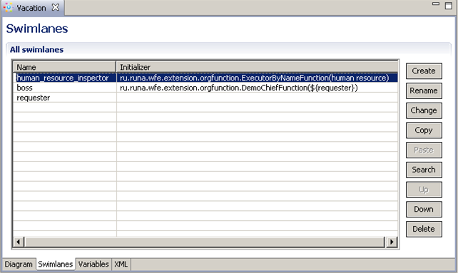
Add "boss" swimlane, specify initializer DemoChiefFunction with "requester" as parameter.
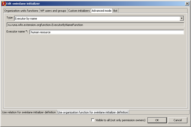
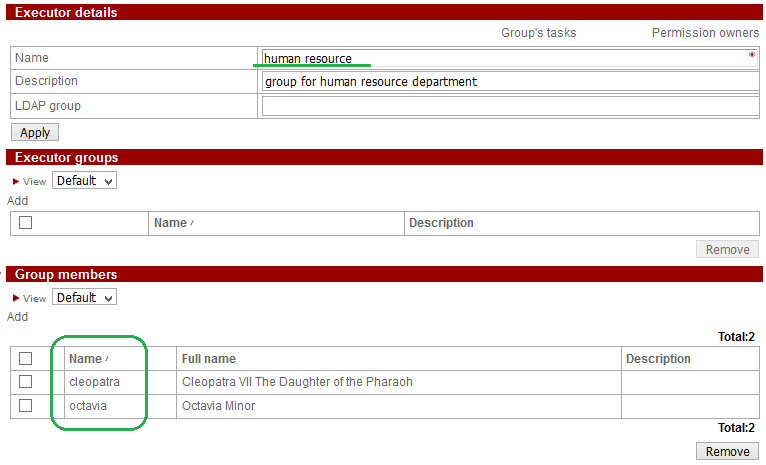
Similarly create "human_resource_inspector" swimlane. Use ExecutorByNameFunction initializer function with group "human resource" as parameter.
Open "graph" tab again, select the start state “Request for a vacation”, in its properties click on right part of the Swimlane\Value property and in the presented list select "requester". Similarly set swimlanes to the other states.
Variable Creation
Variables description and initialization
| There are the following variables in the process: |
| Variable | Type | Description |
| since | Date | Date of the vacation start |
| till | Date | Date of the vacation end |
| reason | String | Reason |
| comment | Text | Comment |
| boss_comment | Text | boss comment |
| bossDecision | Boolean | boss decision |
| human_resource_inspector_comment | Text | Human resource inspector comment |
| humanResourceInspectorCheckResult | Boolean | The result of HR inspector check |
| official_order_number | String | Order number |
| official_order_date | Date | The order date |
Variables
- since
- till
- reason
- comment
must be initialized in the start node “Request for a vacation”.
Variables
- boss_comment
- bossDecision
must be initialized in the “Evaluate a request” activity node.
Variables
- human_resource_inspector_comment
- humanResourceInspectorCheckResult
must be initialized in “Check rules and technologies” activity node.
Variables
- official_order_number
- official_order_date
must be initialized in “Make an official order” activity node.
Variable creation
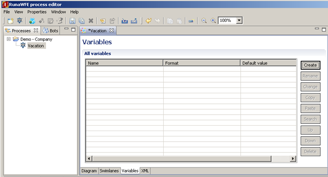
Click on "Variables" tab. Click on "Create" tab.
Type the variable name "since", then choose Date as format.
Similarly create all the rest of the business process variables.
Creating a condition for the Exclusive gateway
Condition description
There are two Exclusive gateways in this process: “Is approved?” and “Is correct?” that we need to provide conditions for.
“Is approved?” gateway:
If the bossDecision variable value equals to "true", the control is passed to «Check rules and technologies» activity node. Otherwise the control is passed to «Notify of rejection» activity node.
“Is correct?” gateway: If the humanResourceInspectorCheckResult variable value equals to "true", the control is passed to the Parallel gateway (a split to simultaneous tasks “Submit a hardcopy request” and “Receive a hardcopy request”). Otherwise the control is passed to «Evaluate a request» activity node.
Creating a condition in Developer Studio
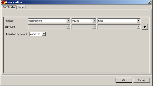
Choose "Diagram" tab, click on the «Is approved?» exlusive gateway, right-click on it to select "change" menu item.
In the shown form for the "rejected" transition select variable bossDecision, select "equals" function and set the value to "false". In the default transition choose "approved":
Click «OK».
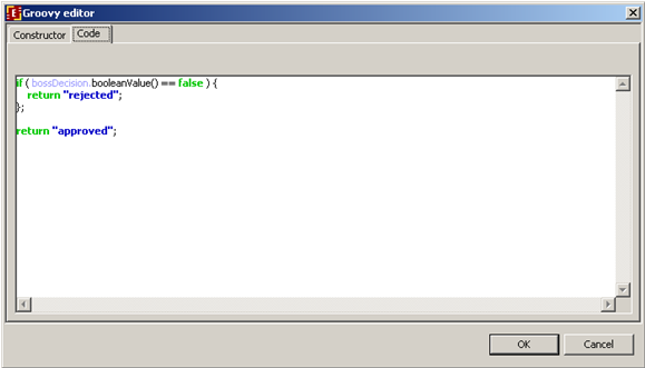
Note. You can see the formula code on the "code" tab and it can be edited there.
Similarly the condition for “Is correct?” gateway is created.
Graphical forms creation
RunaWFE forms description
In Vacation process the html pages with FreeMarker extention (FTL) are used.
| Tags: |
| Freemarker tag | Description |
|---|---|
| Input variable, InputVariable | Creates a field for date-time input |
| Display variable, DisplayVariable | Outputs the value of string variable or number variable (in read-only mode). |
Creating graphical forms with the help of form constructor
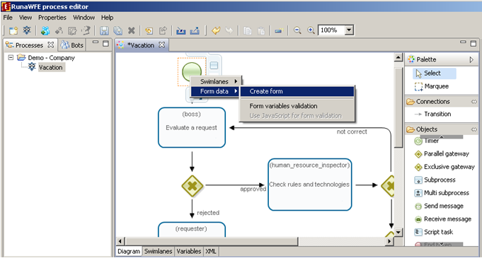
Right click on the start node «Request for a vacation» of the business-process diagram and select in the pop-up menu "Form > Create form":
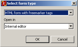
In the drop-down list select form type:
Indicate the form css source in the "code" tab.
Note. Also the form.css is used here. Previously in creating forms for Overtime Work process it was discussed how to create and use this file.
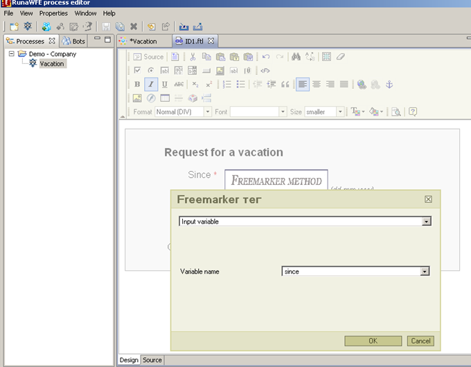
Next on the "design" tab type in the text «Request for a vacation», On the next line type «since *» and click on the first <F> element of the graphical form palette. In the shown form select tag type "Input variable", in the "variable name" field select "since":
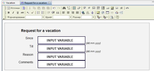
Similarly create elements for other variables input:
- till
- reason
- comment
Note. If you click on "Code" tab, you can see and edit the form code.
Similarly the rest forms for the other activity nodes can be created:
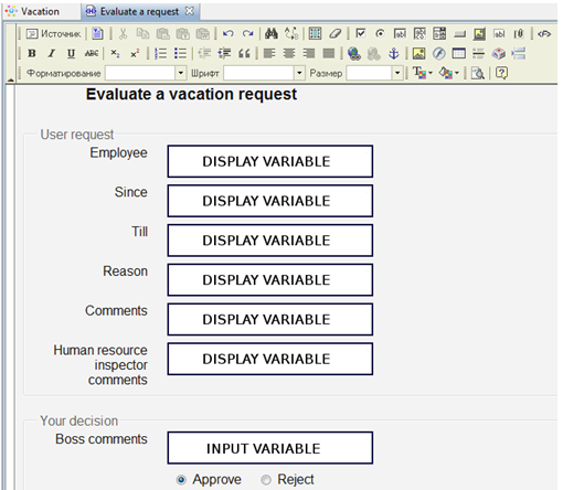
- Evaluate a request
Note. RadioButton element is used to select decision on the form above.
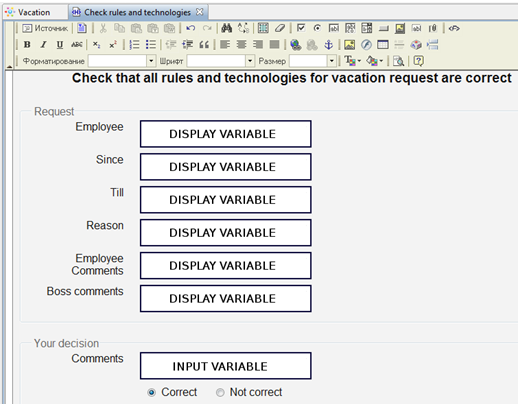
- Check rules and technologies
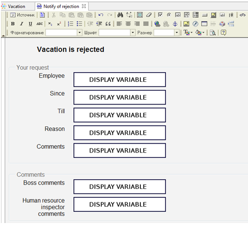
- Notify of rejection
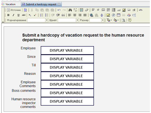
- Submit a hardcopy request
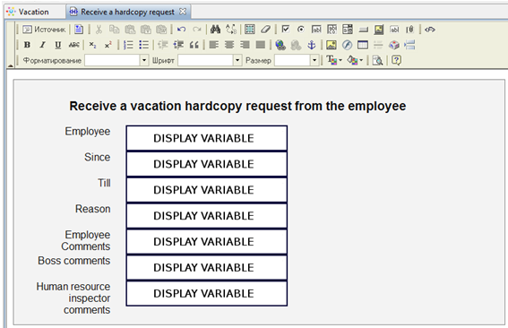
- Receive a hardcopy request
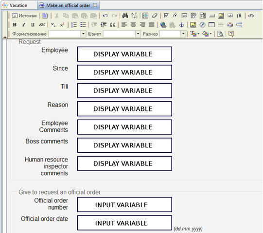
- Make an official order
Creating form variables values validation
Form elements can be required or optional for input. There may be rules for several form elements. For instance, date-since cannot be later than date-till. There may be some limitations specific for types: for numbers it can be more or less than some number and for strings it can be the limitation of the string length, etc.
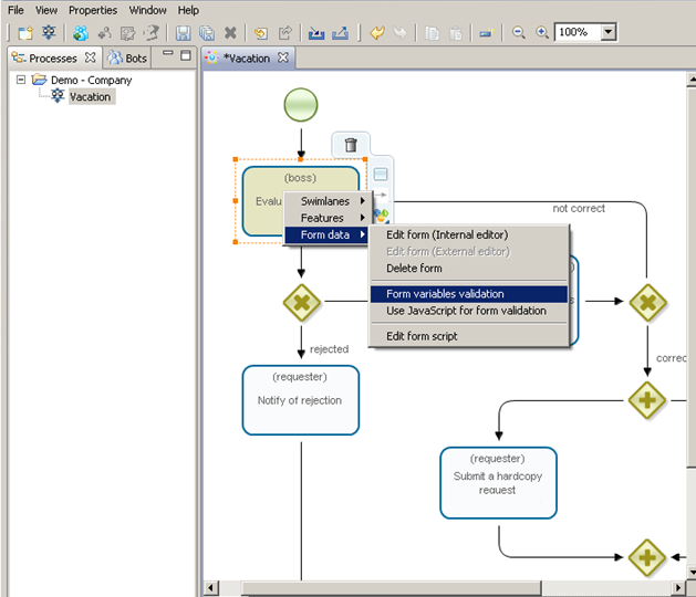
To create start form «Request for a vacation» validations, right click on the node and select "Form > Form variables validation":
In the shown form there will be all the business process variables listed. All the variables that are used in the current form will be marked by checked checkboxes. If unchecked then a variable will not be initialized in this node. For a chosen variable there will be all available validations in the validations list. When a validation is selected then the validation parameters are available for edit below the validations list.
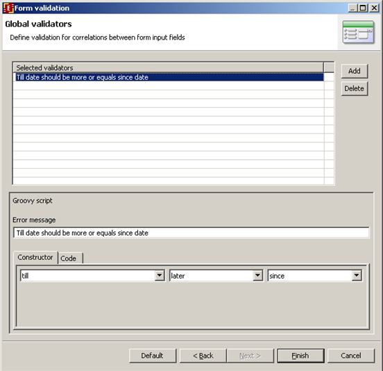
If you want to add validation for several variables together, after setting all the single variable validators click "Next". In the shown editor several variables validation may be created. For instance, date-since cannot be later than date-till.
Deploying created business process into the system
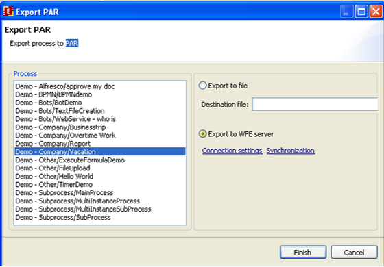
To deploy the process directly to the server it is possible to use "Export process to PAR" with "Export to WFE server" selected:
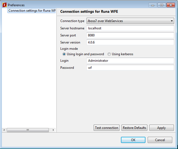
It's necessary to configure the connection first. Select "Connection settings" and input the connection parameters. After setting the parameters press "Test connection" to check if it works.
If all the parameters are set correctly, then it's possible to begin export. Press "Finish" button to proceed. The process will be deployed into the system and it's not necessary to save process in par file before deploying.
Creating process with subprocess
MainProcess and SubProcess processes illustrate how to work with subprocesses.
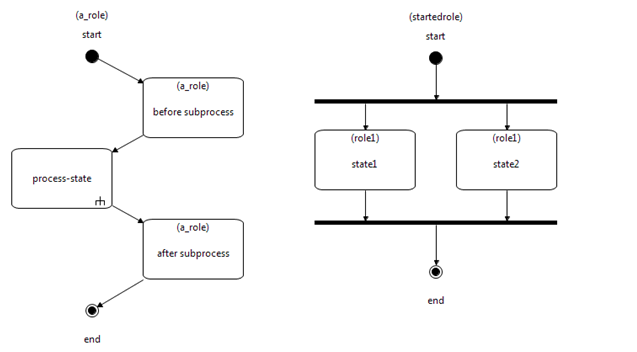
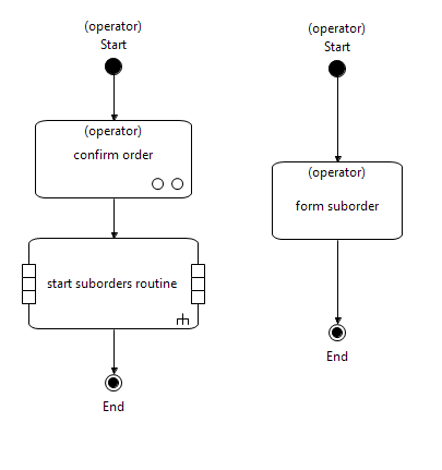
Here are example process graphs (MainProcess left, SubProcess right):
Main process graph contains “process-state” node with special mark at the bottom corner of the element. This is the subprocess node element. When you want to add this element to a graph use "subprocess" element from the palette.
While connecting main process and subprocess you need both processes variable lists. So it is recommended to create subprocess before configuring link between the processes.
There is no difference between subprocess and simple process when you create one. Basically if business logic permits subprocess can be used as independent process as well.
One and the same subprocess can be used in several different main processes.
When main process control flow reaches the subprocess node a new instance of subprocess starts, but no starting form is displayed. Instead the subprocess variables are initialized with the correspondent values from the connected main process.
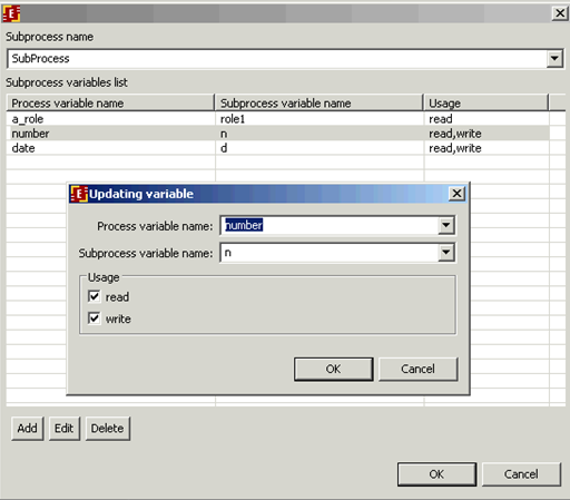
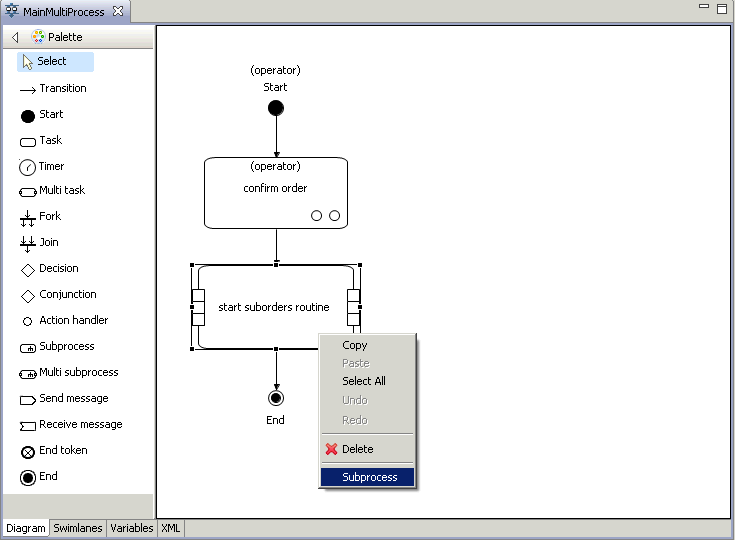
To set the variables correspondence right click on the subprocess node and select "Subprocess" menu item. Then you will see the subprocess setup dialog:
Select the subprocess name from the list of all processes in gpd. Then it is necessary to set the correspondence between main process and subprocess variables and specify variable usage type.
Swimlanes can be also linked.
Usage type "read" means that main process variable will be read and written into the subprocess variable.
Usage type "write" means that main process variable value will be rewritten with the value of the corresponding subprocess variable after the subprocess finishes.
# Creating process with multi subprocess
The demo process MainMultiProcess and its subprocess SubMultiProcess are created to illustrate how multi subprocesses work. The graphs of the processes are below (MainMultiProcess left, SubMultiProcess right):
When MainMultiProcess reaches multi subprocess node several instances of SubMultiProcess start. The number of the subprocess instances is dynamically determined.
In order to set up the link between parent process MainMultiProcess and its subprocess SubMultiProcess it's necessary to pick “Subprocess” option from the popup menu on the Multi subprocess node, in "subprocess name" field put the right subprocess name:
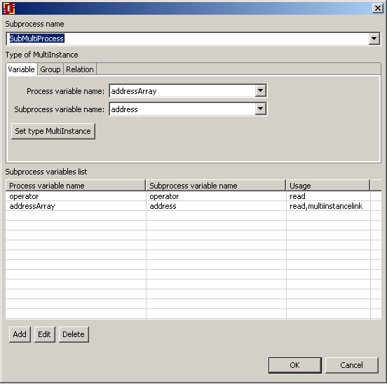
You will see configuration window:
Choose the multi-instance type:
- Variable;
- Group;
- Relation;
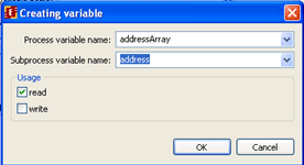
There is a specialized tab for each type. After the type parameters are set the list of process and subprocess variables mapping is filled. To add a variable to the list press "Add" button and choose variables from the lists of process and subprocess variables in the dialog window:
Indicate the variable usage:
- read;
- write;
If «write» usage option is chosen, then after the subprocess is over the mapped variable value from each multi subprocess instance will be written into the multi instance variable of type list of the parent process. Mapped variables are listed in the table. To edit them use the buttons "Add","Edit" and "Delete".
# Choosing multi subprocess type
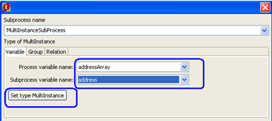
In order to set the selected type of multi subprocess instance you must press the button "Set type MultiInstance".
# Multi subprocess by list variable
In case of multi subprocess a mapping is set between a variable of list(type) format (multi subprocess instance variable) of main process and a variable of simple type (not list) of the subprocess. When multi subrocess instances start each value from the list is written into the correspondent variable of the subprocess, so each subprocess has its own value. The number of subprocesses that start is determined by the list length. Besides the list variable values other main process variables values can be read from the main process in a usual way. The values are simply copied to subprocesses.
For example for the MainMultiProcess:
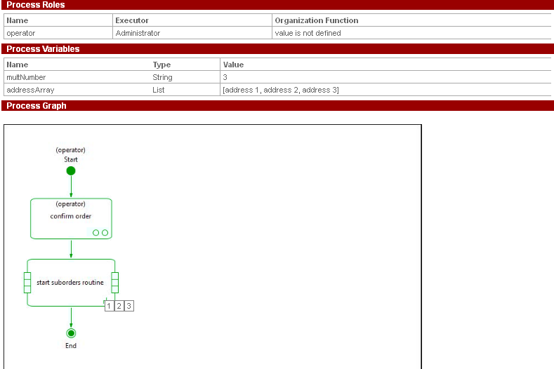
addressArray - multi-instance variable which is mapped to address variable in subprocess. When subprocesses start in «start suborder routine» there is as many subprocess started as the number of addresses in the addressArray. In each subprocess there is its own value of the address variable. Variable operator is copied to every created subprocess instance.
Note: In order to open subprocess instance properties click on the little square with number on the multi subprocess node of the main process graph. The total number of the squares is equal to the number of subprocesses.
In order to return to the main process properties use the same way as with simple subprocesses (via the name of the main process in the upper part of the process instance properties).
# Multi subprocess by group
If it is necessary to create an instance of subprocess for each member of the group when control flow comes to the multi subprocess node then use multi subprocess by group. In order to configure it click "Group" tab of the multi subprocess settings and set the group name. To do so you can use either a constant value or a variable (of String or Group type) which contains the group name during the business process execution. Group name parameter must be linked with a variable in the subprocess.
Also you can add other variables to the mapping. In case you add list variable the following rule applies. In case the number of list elements is not equal to the number of subprocesses the excess elements will be ignored, or the variables in subprocess which lack correspondent list element value will not be initialized.
When subprocesses end all list parameters with write usage type are filled with values and are returned to the main process.
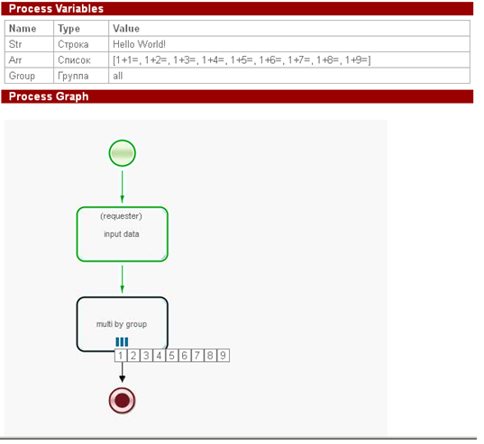
Let´s consider an example of multi subprocess by group:
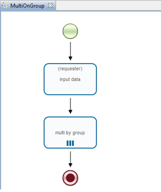
Let´s create business process MuliOnGroup like shown below (BPMN is used here):
Create swimlane "requester" without initializer (it will be initialized by the user who starts business process)
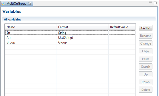
Variables:
- Str – string variable
- Arr - List(String)
- Group – variable of group type
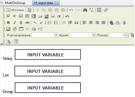
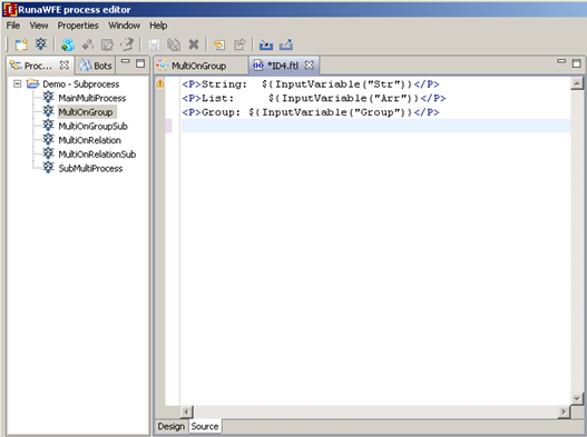
In the "input data" node let's create the following form:
Use tag "variable input" for variables Str, Arr, Group
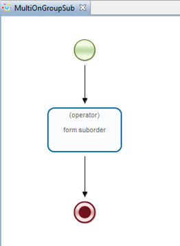
Now let's create subprocess MultiOnGroupSub:
Create swimlane "operator" without initializer
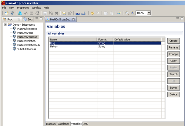
String variables:
- Msg - message from the main process
- Return - contains a value of array element (Arr) from the main process, it can be edited in the subprocess form and when the subprocess instance finishes the value will be copied back into the main process array element.
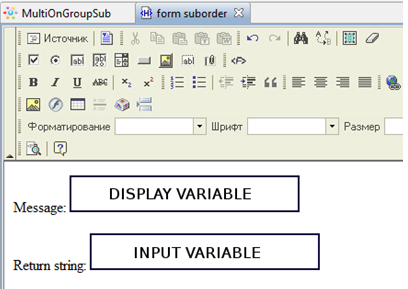
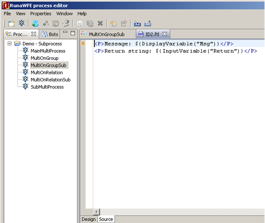
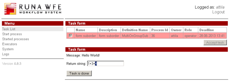
Let's create a form for Msg variable output and Return variable input using "variable output" and "variable input" element.
Back to the main process.
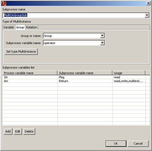
Right-click on multi subprocess node and select "subprocess" menu item. Select MultiOnGroupSub as subprocess. Choose multi instance type "Group" and set the variables mapping:
Here we use group variable "Group", string parameter Str and list Arr are passed to the subprocess. The "Return" variable values are passed back to the Arr list so "write" usage type is selected.
In order to check if the process is developed correctly let's run it.
The process execution:
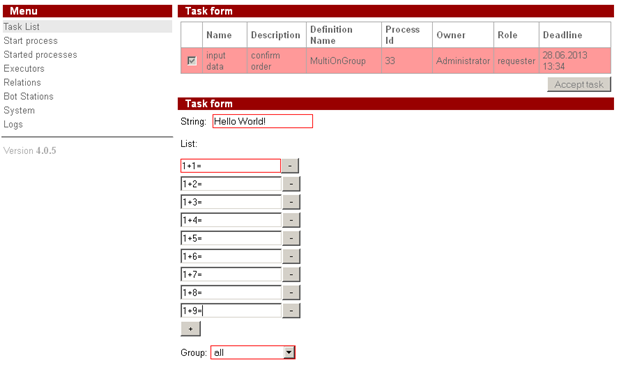
- The executor who starts the main process types in the parameters values that are copied to subprocesses (message and list)
- chooses the executors group
- for each executor from the chosen group a subprocess instance is created. String parameter (message) and list element values are copied to each subprocess;
- the parameters are shown in form in subprocess;
- each executor edits text field to change "Return" variable value;
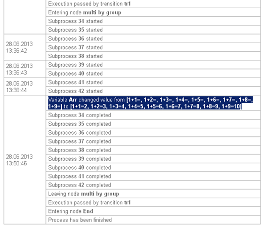
- all changes are saved in correspondent elements of Arr list and are returned to the main process;
# Multi subprocess by relation
If you choose to link multi subprocess by relation there are as many subprocess instances created as the number of elements in the left side of the relation with given parameters. Relation parameters are its name and its right side. You can specify variable which will contain the desired value or you can use constant value.
When all subprocesses end all values with "write" usage type will be returned to the main process. If you select "write" usage type you must specify the main process variable of list(array) type.
Here's an example of the multiprocess by relation.
Let's create MultiOnRelation process on the basis of previous example MultiOnGroup by editing it:
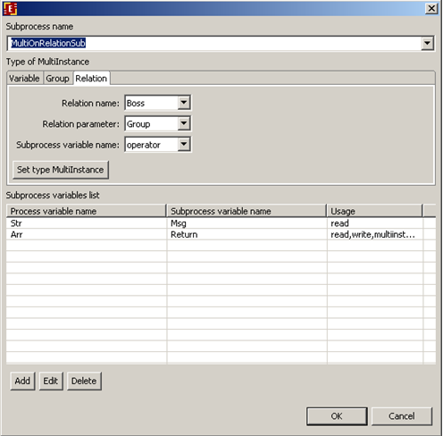
Select "Relation" tab in multi subinstance configurator (right-click on the multi subinstance node and choose subprocess to get there), In "Relation name" field type in "Boss", and in "Relation parameter" choose variable named "Group", the name of the variable in subprocess is "operator". For each subprocess this variable will contain different value - one of the left side of the relation.
The same parameters as in previous example are passed to the subprocess.
Let's export and run the process in order to check it.
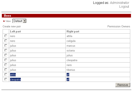
But firstly let's add the following pairs to the "Boss" relation:
That means that attila and cleopatra users are chiefs of the users from "all" group
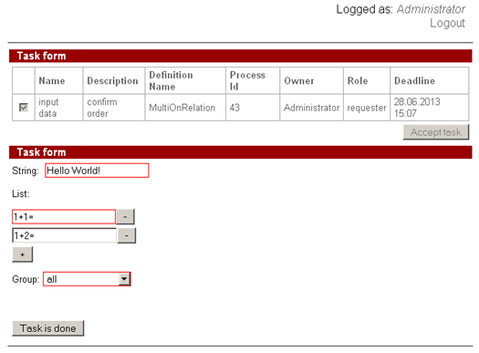
Start the process, in "input data" node form input the necessary parameters, in the drop-down list select "all" group.
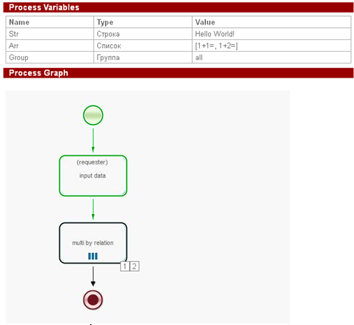
The number of users that meet relation parameter is 2, so let's form the list with 2 elements and execute task.
As you can see there were 2 subprocess instances created and it corresponds to the selected relation parameters. Let's execute subprocess task by attilla and cleopatra and change "Return" parameter value while we at it.
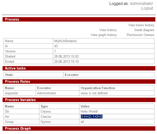
After subprocesses end let's check the values of the returned parameters in the main process:
As you can see the edited parameters are present in the correspondent elements of "Arr" list.
# Creating process with multi task
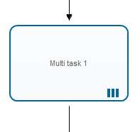
Multi task - a special type of additional node.
It is similar to the "Task", but unlike the "Task" it generates several tasks at once.
If the "All tasks should be executed" mode is selected - control passes to the next node on the outgoing transition only after all "Multi" tasks have been completed. You can also select the "Only first task should be executed" mode.
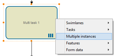
Mode selection is available in the menu item "Tasks".
Tasks can be assigned to one or more executors. The settings for multiple instances is available in menu item "Multiple instances".
# Multiple instances defined by list variable
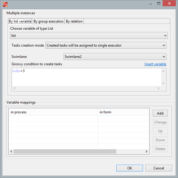
Multiple instances of a multi task can be defined by a variable of the "List" type. There are two options for task assignments:
- created tasks will be assigned to single executor
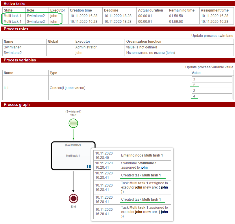
All task instances will be assigned to the executor of the selected swimlane. It is required to select a swimlane and list variable. The number of task instances will correspond to the number of list elements.
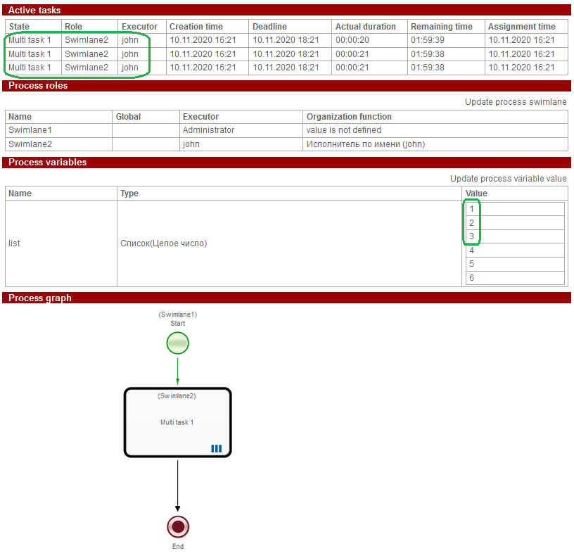
It is possible to set a Groovy condition to create task. You can use the index (index) or value (item) of the list item in the condition.
For example, we use the condition "index<3" i.e. tasks will be created for list items, the index of which in the list does not exceed 3. All task instances will be assigned to the "Swimlane2".
Another example. Condition of creating tasks - "item! = 3"
Tasks will be created for list items whose value is not equal to '3'
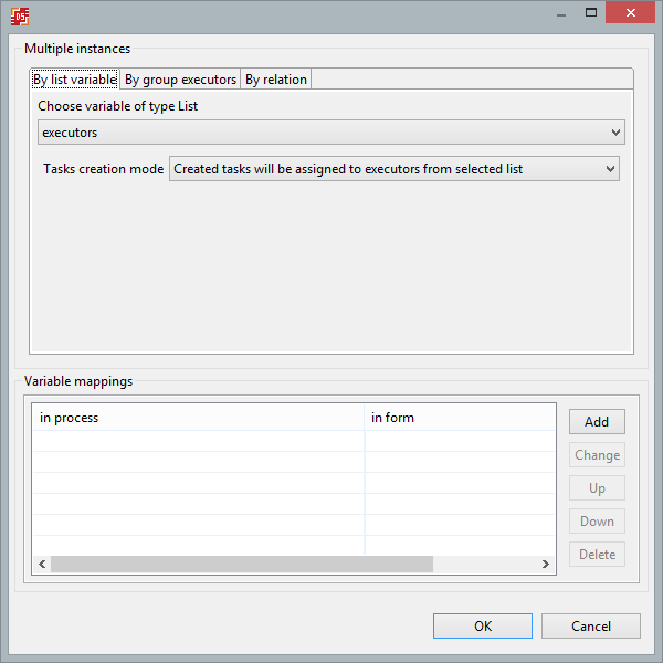
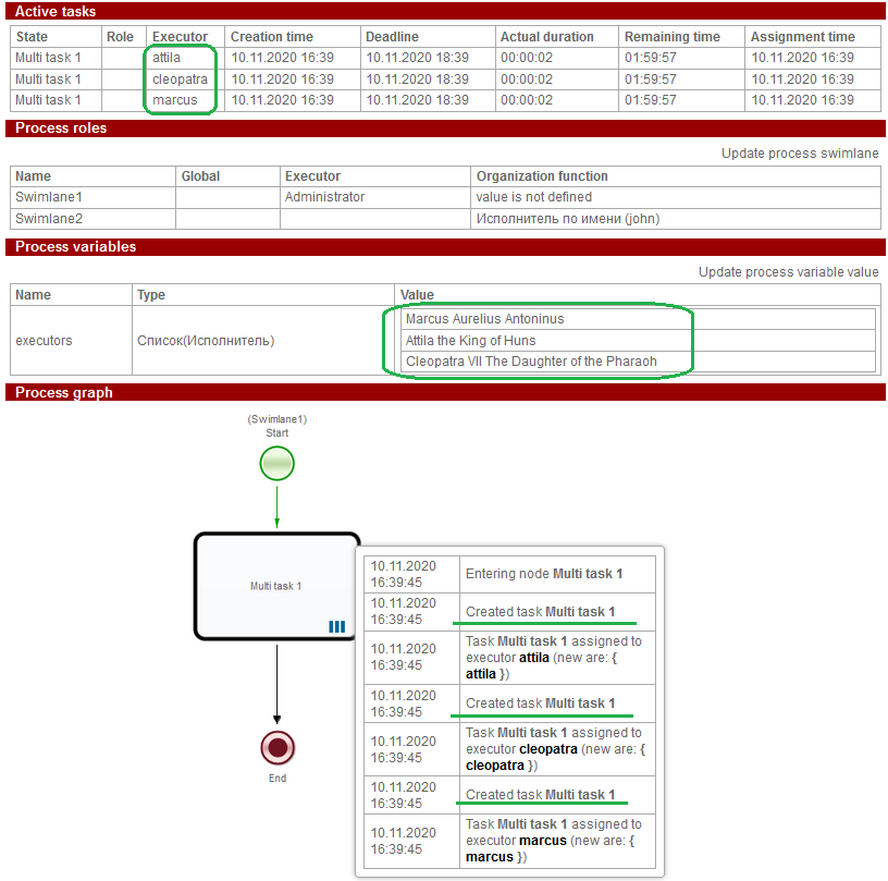
- created tasks will be assigned to executors from selected list
The variable must be of the List(Executor) type, tasks are created unconditionally.
For example
# Multiple instances defined by group executors
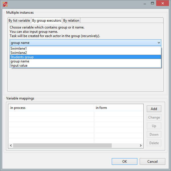
Select a variable containing a group or group name. Only variables of type Executor, Group, String, Swimlane are available for selection. Also the name can be set manually.
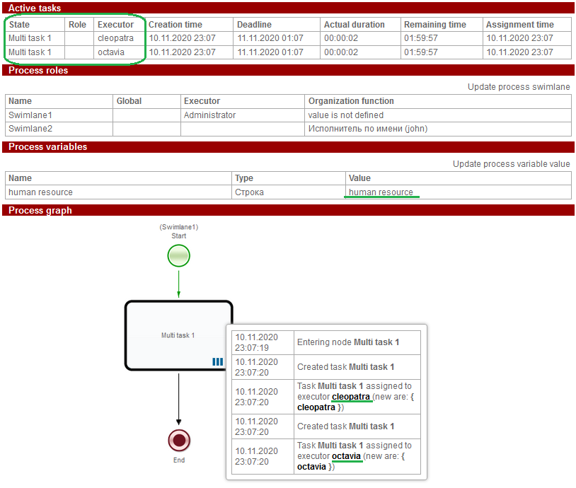
Tasks are created unconditionally and will be created for each actor in the group (recursively).
# Multiple instances defined by relation
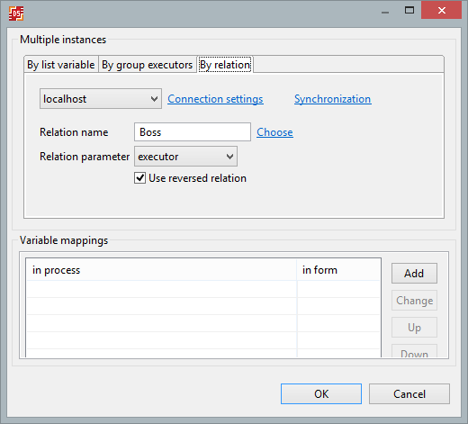
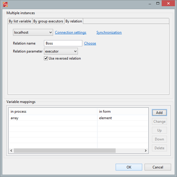
By default multi task used a reversed relation ie as many instances of task are created as there are elements on the right side of the relation with the specified parameters. Relation parameters are the name of the relation and its left side. If you want use not reversed relation, you can uncheck "Use reversed relation" option.
Variables of the type Group, User, Executor, and String (in this case, the variable must contain the name of the executor) can be used as a parameter of the relation.
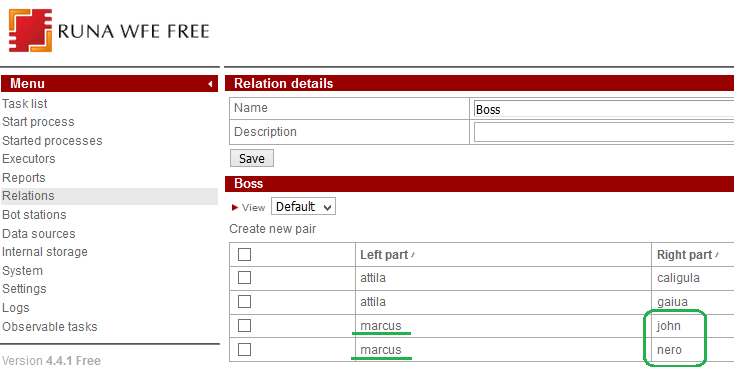
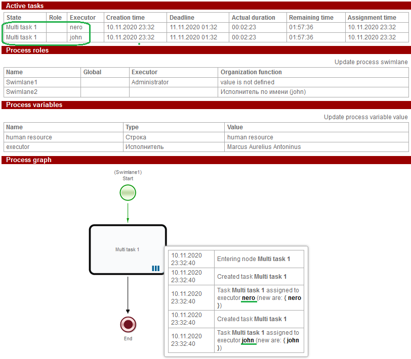
For example, let's start a multi task on the reversed relation "Boss", with the "executor" parameter, initialized by the "marcus" executor.
# Variable mappings
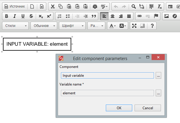
In the "Variable mappings" section, you can define the name of the array element passed to the multi task instance. Under this name, the variable can be used on form files.
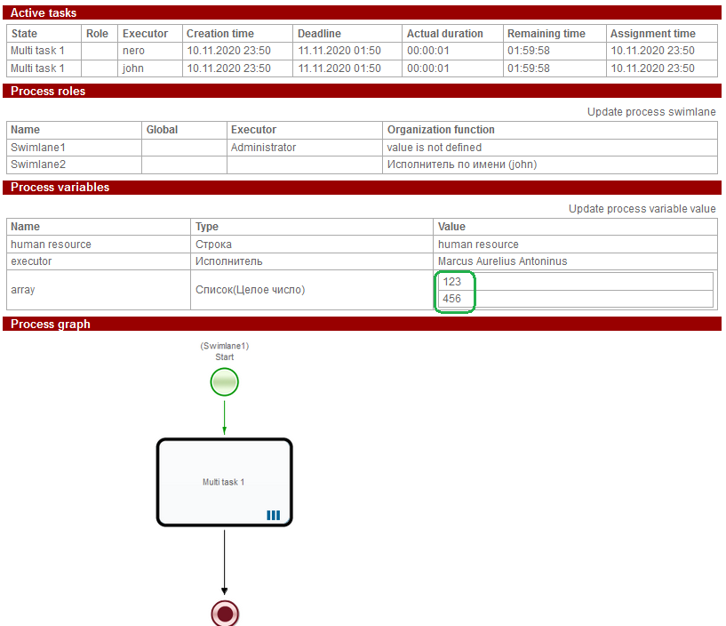
For example, the list item of the "Array" variable is mapped to the "element" variable which is used on the form in the "Input variable" component
Two instances of multi task
The tasks were assigned to "john" and "nero".
# Generation of regulation text 4.1.2+
Regulation is a business process description in a form of an official document.
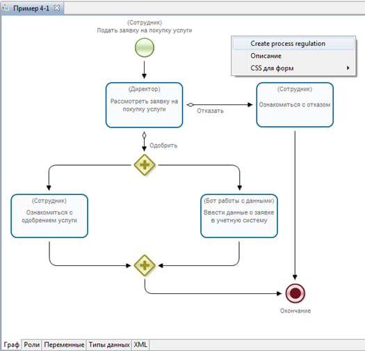
To generate regulation text automatically choose "Create process regulation" from the context menu.
Note. This menu item is available only if the process has no errors.
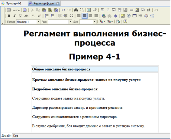
A new tab is open with graph text description with the following structure:
- Business process name
- Business process short description (it's added to the document only if process short description is filled)
- Business process full description (it's added to the document only if process full description is filled)
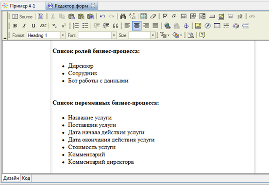
- List of business process roles
- List of business process variables
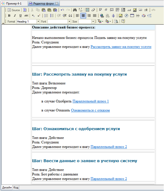
- Business process actions descriptions in an order of addition to the diagram (except Start and End elements)
Using ActionHandlers
It is possible to execute java-code when certain events happen. For example when control flow follows a certian transition. Simple java code script can be placed into configuration of already existing GroovyActionHandler of BSHActionHandler (see in the next section). Only when it is not enough a custom ActionHandler with more complex code has to be written. The business logic code must be placed in execute() method of a class that implements ActionHandler interface. Then it is necessary to load new ActionHandler to the system. (See here)
In Developer Studio in order to use action handlers in the process (in JPDL) do the following:
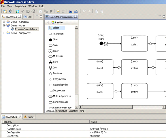
1. Make sure that in Properties main menu "Show action handlers" option is chosen. When this option is turned on "Action handler" element is present in the palette.
2. Select "Action handler" from the palette.
3. Place element on the graph. You can place action handler on transition or right on the node.
Click on transition or node and a circle icon of action handler will be added to that element of the graph.
4. Select "Select" element from the palette. Click on the action handler from the graph to select it then choose "Properties" tab below graph and choose ActionHandler class there.
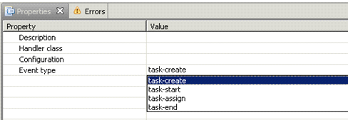
5. Next let's create action handler configuration by clicking on the button next to the "Configuration" line in the "Properties" tab. If you add action handler to a node you can choose the event which triggers action handler. Use "Event" property for it and select one of the following options:
- task-create
- task-start
- task-assign
- task-end
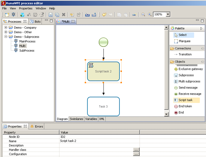
If you use BPMN to develop a process then there's "Script task" in the palette.
In this element properties you also can find action handler class and configuration properties that are used similarly to JPDL.
See handler reference for details.
How to initialize swimlanes
Initializing swimlane with the help of ExecutorByName function
Swimlane initialization function ExecutorByName, as its name states, initializes swimlane with the executor (an actor or a group) whose name is passed as a parameter into this function.
As an examle let's create a new swimlane "human resource inspector" in "Vacation" demo-process. Open Vacation process in Developer Studio. On the swimlane tab click create button. Type "human resource inspector" as the new swimlane name. Click Ok.
Select the role name from the list, then click "change" button, in the appeared dialog choose "Advanced mode" tab. Choose type "Function 'ExecutorByName'". As the executor name parameter enter "human resource". Click Ok. The new swimlane initializer is defined now.
Initializing swimlane with a function that takes a business process variable as a parameter
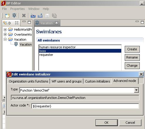
Let's create a swimlane initializer for "boss" role in the "Vacation" demo-process. Open "Vacation" process in GPD. On the swimlane tab window click "create" button. In the appeared dialog type "boss" for the name of new swimlane. Click Ok. Select the "boss" swimlane in the list and click "change" button. Select "Advanced mode" tab. Choose type "Function 'demoChief'" and type ${requester} as actor code. Thus the demoChief function will be used to initialize the boss swimlane and the paramenter of the function will be the value of the business process variable named "requester".
Note: when you using the value of the business process variable as swimlane initialization function parameter always use the syntax ${variable_name}.
Form validation
Using validation
On the context menu for the form in process diagram click 'Form validation' menu. It will create default validation file with all variables present on the form checked. Customize validation file for your needs. You can optionally use client-side validation for form based on JavaScript. Check menu 'Use JavaScript validation' in the same context menu. It will be accesible after validation file is created.
Concepts
Validators can be categorized by 2 types: Field Validator (checks if the field value is valid) and Non-Field Validator (It’s not attached to field and checks input data over all fields).
If value of the field is null validation of the Field Validator attached to that field work unless ‘required’ validator is checked, then validation fails.
Base validators
| Validator type | Description + Example |
| date | Validator that checks if the date supplied is within a specific range.
min - the min date range. If not specified will not be checked. max - the max date range. If not specified will not be checked.
<field name="birthday"> <field-validator type="date"> <param name="min">01.01.1990</param> <param name="max">01.01.2000</param> <message>Birthday must be within ${min} and ${max}</message> </field> </field> |
| double | Validator that checks if the double specified is within a certain range.
(if parameter is not specified, it will not be checked) minInclusive - the minimum inclusive value maxInclusive - the maximum inclusive value minExclusive - the minimum exclusive value maxExclusive - the maximum exclusive value
<field name="percentage"> <field-validator type="double"> <param name="minExclusive">0.123</param> <param name="maxExclusive">99.98</param> <message> It needs to be between ${minExclusive} and ${maxExclusive} </message> </field-validator> </field> |
| Validator checks that a given String field is a valid email address.
The regular expression used to validate that the string is an email address is: \\b(^[_A-Za-z0-9-]+(\\.[_A-Za-z0-9-]+)*@([A-Za-z0-9-])+((\\.com)|(\\.net)|(\\.org)|(\\.info)|(\\.edu)|(\\.mil)|(\\.gov)|(\\.biz)|(\\.ws)|(\\.us)|(\\.tv)|(\\.cc)|(\\.aero)|(\\.arpa)|(\\.coop)|(\\.int)|(\\.jobs)|(\\.museum)|(\\.name)|(\\.pro)|(\\.travel)|(\\.nato)|(\\..{2,3})|(\\..{2,3}\\..{2,3}))$)\\b
<field name="myEmail"> <field-validator type="email"> <message>Must provide a valid email</message> </field-validator> </field> | |
| expression | A Non-Field Level validator that validates based on BSH expression supplied.
expression - the BSH expression to be evaluated against the variables (Must evaluate to a Boolean)
<validator type="expression"> <param name="expression"><![CDATA[number > number2]]></param> <message>Failed to meet BSH Expression</message> </validator>
|
| number | Validator that checks if the integer specified is within a certain range.
(if parameter is not specified, it will not be checked) min - the minimum value max - the maximum value
<field name="age"> <field-validator type="int"> <param name="min">20</param> <param name="max">50</param> <message>Age needs to be between ${min} and ${max}</message> </field-validator> </field> |
| regex | Validates a string field using a regular expression.
expression - The RegExp expression REQUIRED caseSensitive - Boolean (Optional). Sets whether the expression should be matched against in a case-sensitive way. Default is true. trim - Boolean (Optional). Sets whether the expression should be trimed before matching. Default is true.
<field name="myStrangePostcode"> <field-validator type="regex"> <param name="expression"><![CDATA[([aAb][123][eEfF][456])]]></param> </field-validator> </field>
|
| required | Checks that field value is not null |
| requiredstring | Validator checks that a String field is non-null and has a length > 0. (i.e. it isn't ""). The "trim" parameter determines whether it will trim the String before performing the length check. If unspecified, the String will be trimmed.
trim - trim the field name value before validating (default is true) <field name="username"> <field-validator type="requiredstring"> <param name="trim">true</param> <message>username is required</message> </field-validator> </field> |
| stringlength | Validator checks that a String field is of a certain length. If the "minLength" parameter is specified, it will make sure that the String has at least that many characters. If the "maxLength" parameter is specified, it will make sure that the String has at most that many characters. The "trim" parameter determines whether it will trim the String before performing the length check. If unspecified, the String will be trimmed.
maxLength - The max length of the field value. Default ignore. minLength - The min length of the field value. Default ignore. trim - Trim the field value before evaluating its min/max length. Default true
<field name="myPurchaseCode"> <field-validator type="stringlength"> <param name="minLength">10</param> <param name="maxLength>10</param> <param name="trim">true</param> <message>Code needs to be 10 characters long</message> </field-validator> </field> |
| url | Validator checks that a given field is a String and a valid URL
<field name="myHomepage"> <field-validator type="url"> <message>Invalid homepage url</message> </field-validator> </field> |
DTD for the form validation file
<?xml version="1.0" encoding="UTF-8"?>
<!ELEMENT validators (field|validator)+>
<!ELEMENT field (field-validator+)>
<!ATTLIST field name CDATA #REQUIRED>
<!ELEMENT field-validator (param*, message)>
<!ATTLIST field-validator type CDATA #REQUIRED short-circuit (true|false) “false">
<!ELEMENT validator (param*, message)>
<!ATTLIST validator type CDATA #REQUIRED short-circuit (true|false) "false">
<!ELEMENT param (#PCDATA)>
<!ATTLIST param name CDATA #REQUIRED>
<!ELEMENT message (#PCDATA)>
<!ATTLIST message key CDATA #IMPLIED>
Choosing process graph language, swimlane display on process graph in BPMN
It is necessary to choose language (JPDL or BPMN) during new process creation.
If you choose JPDL, swimlane is displayed on the graph elements. In BPMN you can choose how to display swimlane:
If you select "No" then swimlane will be displayed on the graph elements just like in JPDL:
You can choose swimlane via context menu on the graph node or via "Swimlane" property on the "Properties" tab of the node.
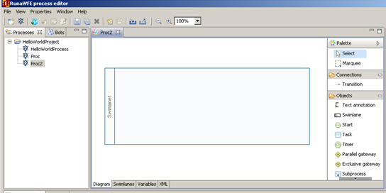
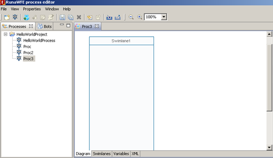
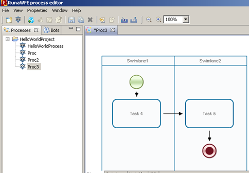
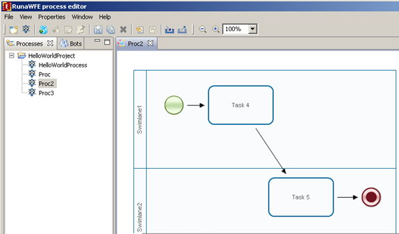
Another option is to display swimlane on the process graph. In this case the options are to display it "horizontally" or "vertically". There's no need to create swimlane manually. You can place swimlane element on the graph and the swimlane is created automatically. It is displayed in either horizontal or vertical area depending on what was chosen during process creation.
You should place process nodes into this area and the swimlane will be chosen automatically.
Starting from version 4.0 you cannot change language after process creation.
Problems while using form editor
Form editor is a built-in browser (IE for Windows) and it extensively engages JavaScript.
For Windows
Error message dialogs appear recursively
It can be solved by turning off JavaScript debugging in IE browser properties.
No tool panel (empty window in Design mode)
It happens because of security settings of the IE browser.
Start editor, open form, start IE and browse http://localhost:48780/fckeditor.html (in case of CKEditor 3: http://localhost:48780/ckeditor.html). The content of the page must match. Now change the browser settings in a way that allows this page to be loaded correctly. There can be several problems (JavaScript is turned off, running JavaScript is prohibited in this zone, etc). After it the form editor must work correctly in Developer Studio.
В Linux
You can find some advice on forum:
GPD HTML visual editor on Linux
Html form designer not loaded in Linux
# Connecting to WFE-server
Some operations with server can be performed from editor:
- business process import/export
- bots import/export
- actors and groups import for swimlane initialization
- relations import for swimlane initialization
There's a single server connection setting for all these operations (Settings -> Integration -> RunaWFE server).
Depending on connector type the values of the settings might differ.
connection properties
| Jboss4 via RMI (Connects to RunaWFE server on Jboss4) | Jboss4 via web services (Connects to RunaWFE on Jboss4) | Jboss7 via web services (Connects to RunaWFE on Jboss7) | |
| Computer name | IP or computer name | ||
| Port | RMI port (default 10099) | HTTP port (default 8080) | |
| Server version | unused | used to form WSDL URL | |
| Authentication mode | |||
| Login | |||
| Password | |||
Note. WSDL URL for Jboss4 via web services: http://computerName:Port/runawfe-wfe-service-ServerVersion/ServiceNameServiceBean?wsdl
Note. WSDL URL for Jboss7 via web services: http://computerName:Port/wfe-service-ServerVersion/ServiceNameWebService/ServiceNameAPI?wsdl
